Introduction
Biscuit joints are supposed to be the forgiving joint. You cut a slot in each edge, glue in a compressed beech biscuit, and the two boards pull into line. In practice, many home woodworkers end up with a panel that is stepped by a millimeter or two at every joint — just enough to catch a fingertip and demand an afternoon of sanding.
The culprit is almost never the biscuit. It is slot placement. A biscuit joiner registers off the face of the board, and if the tool rocks, tilts, or sits at a slightly different height on the second board, the two slots no longer share a centerline. The biscuit then forces the boards out of alignment instead of into it.
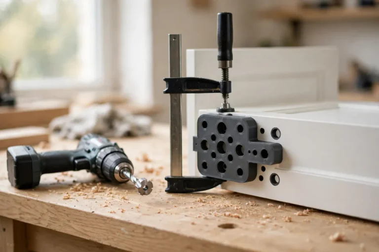
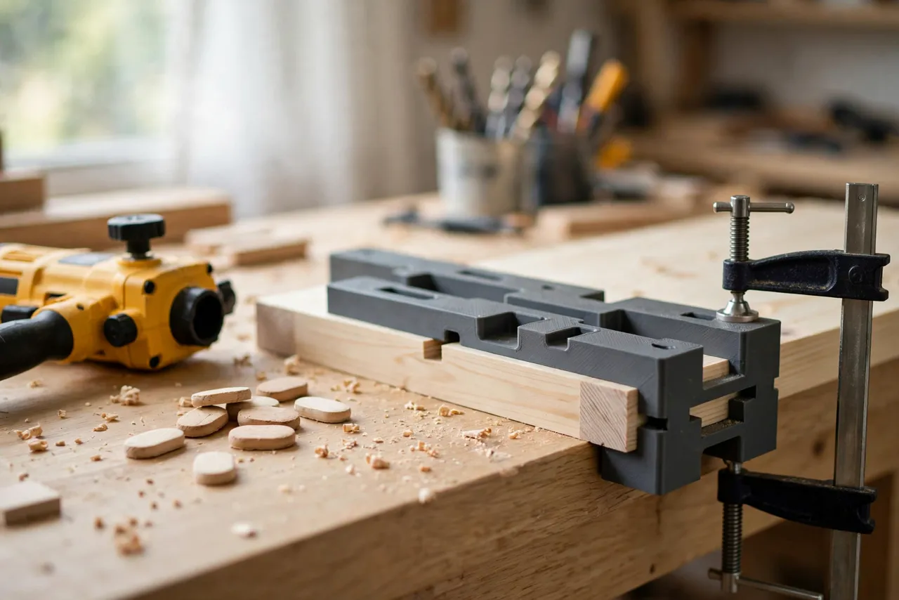
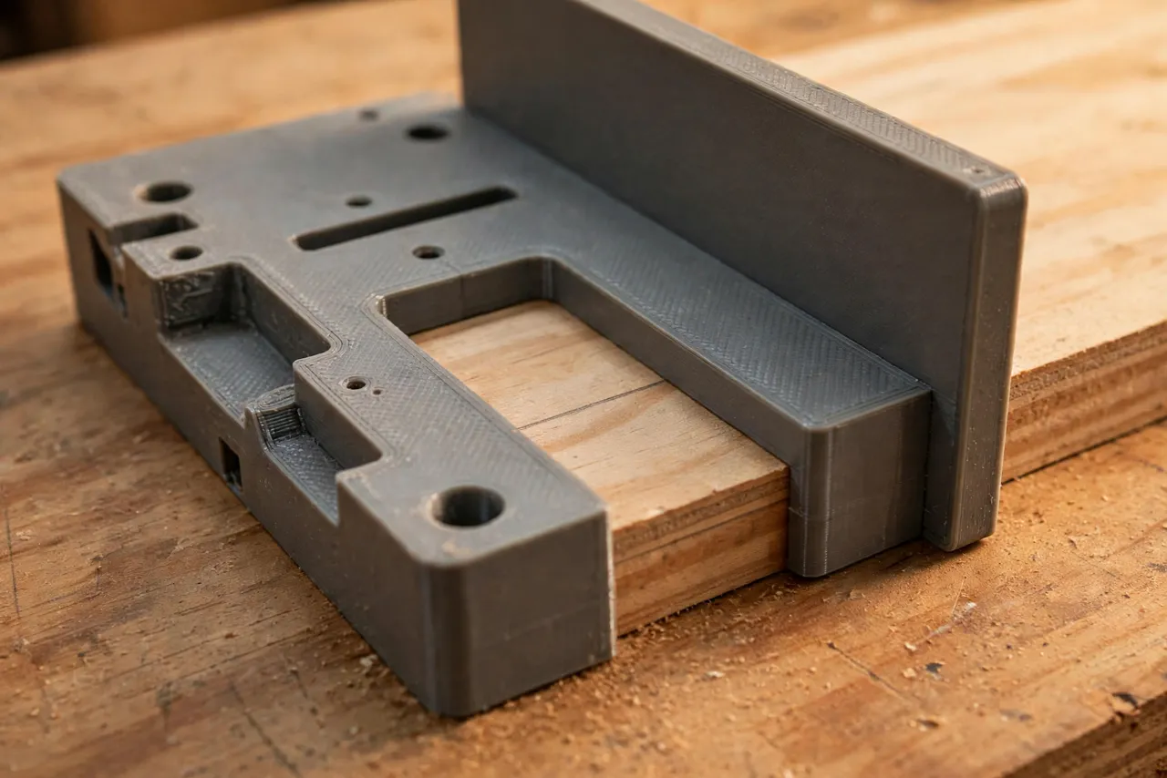
A 3D printed biscuit joiner alignment jig fixes the variable you cannot control by hand alone: repeatable positioning. The jig clamps across the board edge, gives the joiner a flat, square reference surface, and carries center marks that transfer from one board to its mate. Make it once, and every biscuit in a panel lands in the same place relative to the face that matters.
Think of the jig as a layout and registration aid only — it does not carry load, and it never replaces careful measuring on the first board of a glue-up.
What You Need
The jig is a simple, flat part with a fence and a window, sized to fit most home printers in one piece. Split versions work too, if your build plate is small.
Materials and tools
- A home 3D printer with a build area of roughly 150 mm in at least one direction
- PETG filament for a durable jig, or PLA for a first test version
- Your biscuit joiner, plus the biscuit size you use most (usually size 20 for panels)
- A few biscuits and some scrap boards of the same thickness as your project
- A tape measure or calipers, a pencil, and a small square
- Two small clamps, sandpaper or a small file, and wood glue for test joints
PETG is the better keeper: it resists the clamping pressure and the warmth of a garage workshop without cracking. PLA is fine for proving the fit, but store it away from direct heat.
Suggested print settings
- Layer height: 0.20 mm for a good balance of speed and accuracy.
- Walls: 4 perimeters minimum — the fence and the joiner rest face take the pressure.
- Infill: 40 to 50 percent, grid or gyroid, so the jig does not flex under a clamp.
- Top and bottom layers: 4 or more, for a smooth face against the board.
- Orientation: Print flat, board-facing side down, for the flattest reference surface.
- Supports: A well-designed jig needs none.
Print a test version first and check it against your actual joiner before printing the keeper.
Design Considerations
You can model this jig in any basic CAD program. It is essentially a wide, flat plate with a fence on one edge, a window or notch that frames the joiner, and clear center marks.
1. The reference fence
The fence is the heart of the jig. It hooks over the board edge and registers against the face of the board — the same face the joiner itself references. Give it 10 to 15 mm of contact depth and keep its inside corner square. A rounded or rough corner lets the jig rock, and every slot inherits that error. Lightly sand the fence face after printing so it sits flush with no high spots.
2. The joiner rest and window
The joiner needs a flat area to sit on while you plunge, plus a window or open slot that shows the board edge and your pencil mark. Size the window to your joiner’s base plate, with about 1 mm of clearance per side — snug enough to stop sideways drift, loose enough that the tool slides in without catching. Add a small raised lip at the back of the rest so the joiner cannot slide backward mid-plunge.
3. Center marks that transfer
Biscuit slots only line up if both boards share the same marks. Build a center notch or a raised rib on the jig that lines up with a pencil tick on the board edge. Better still, add two small V-notches, one on each side of the window, so you can mark from either direction. Some makers add a row of evenly spaced notches along the fence for standard biscuit spacing — handy for long panels, but optional on a first version.
4. Sizing for board thickness
Most panel stock is 18 to 22 mm thick, but shelves and tabletops vary. Two approaches work:
- Fixed fence: Simplest and most rigid, matched to your most common board thickness.
- Stepped fence: Two or three steps on the underside, each matching a common thickness.
If you work with varied stock, print two jigs and mark the thickness on top with a paint pen. Round the outer corners so the jig is comfortable to handle and less likely to chip.
Step-by-Step: Printing and Fitting the Jig
- Measure your joiner — base plate width and length, and the height of its fence relative to the blade.
- Measure your boards at the joint, not at a corner where finish may have built up.
- Model the plate, roughly 180 mm long, 80 mm wide, and 6 mm thick, with fence, rest, window, and center notches.
- Print a test fit. The joiner base should slide into the rest flat, with a small, even gap around it.
- Check the fence against a square board edge — no rocking, no visible gap.
- Clean it up. Remove stringing, sand the fence face, and clear the notches.
- Adjust if needed. Too tight? Open the window by 0.3 mm and reprint. Small iterations are normal.
- Print the keeper in PETG if your test was PLA, using the same file.
Test the jig on scrap before touching project boards. Cut slots in two offcuts, glue in biscuits, and check the joint with a straightedge.
Step-by-Step: Using the Jig for a Panel Glue-Up
- Choose your show face. Mark it on every board — all slots must reference this face.
- Lay out biscuit positions on the first board, spacing them evenly and keeping the outer biscuits at least 75 mm from the ends.
- Mark center ticks on the board edge at each position, using a square from the show face.
- Clamp the jig over the edge, fence flush against the show face, center notch on your tick.
- Seat the joiner in the rest, base flat, and plunge steadily without forcing or rocking the tool.
- Move to the next tick, re-clamping each time. Do not slide the jig along the edge unclamped — that is how slots wander.
- Transfer the ticks to the mating board with a square, then repeat the same process.
- Dry-fit with biscuits before gluing. The boards should meet flush with no step.
- Glue up as usual, biscuits in both slots, and check the panel with a straightedge while the glue is still workable.
Work slowly on the first panel. By the second, the routine feels automatic — and that consistency is what keeps a whole tabletop flat.
Tips for Better Results
- Always reference the same face. Flipping a board mid-panel is the fastest way to create a step.
- Clamp, don’t hold. A hand-held jig shifts during the plunge, however steady your hands feel.
- Brush slots clean before dry-fitting; a crumb of waste can hold a biscuit proud.
- Keep biscuits dry. Swollen biscuits from a damp shop will not seat fully and will push joints apart.
- Test on scrap of the same thickness. A jig proven on 18 mm stock may behave differently on 28 mm stock.
Common Mistakes to Avoid
- Designing from a photo instead of your own joiner. Base plates differ by several millimeters between brands. Measure the tool in your hand.
- Making the window too tight. A joiner that binds in the rest will tilt as you force it, which is worse than a little clearance.
- Skipping the clamp on short boards. Short pieces move the most under plunge pressure.
- Marking from the wrong face. One board referenced off the top and its mate off the bottom guarantees a stepped joint.
- Plunging twice in one slot. A second plunge widens the slot and loosens the biscuit’s grip.
Care, Storage, and When to Choose an Alternative
Brush off dust, store the jig flat or hang it from a peg, and keep PLA versions away from hot cars and radiators. If the fence corner gets dinged, reprinting takes under an hour.
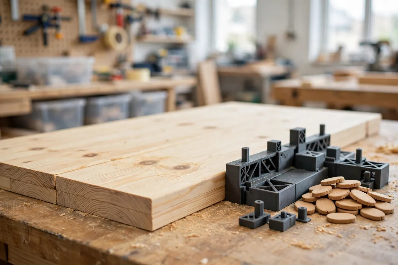
Sometimes a manufactured jig is better. If you cut biscuits all day, work in hardwoods that punish plastic fences, or need hardened guide surfaces for a production run, a metal jig will outlast plastic and hold tighter tolerances. For home panels, shelves, and tabletops in varied sizes, a printed jig is faster, easy to customize, and accurate enough.
FAQ
Will one jig fit every biscuit joiner?
Not quite. The window is sized around one base plate, so a very different joiner may need its own version. The fence and marking system transfer easily between versions, so adapting the model for a second tool is a small job, not a redesign.
Is PLA strong enough, or do I need PETG?
For marking and light clamping, PLA is strong enough and great for testing fit. PETG is the better keeper because it handles clamping pressure, drops, and warm workshops better. Either way, generous walls and infill matter more than the name on the spool.
Can I use the jig with different biscuit sizes?
Yes — the jig positions the slot, and the joiner’s own depth setting chooses the biscuit size. Just keep the spacing sensible: small biscuits need more of them along a long joint, and large biscuits should stay well clear of board ends.
My joints are still stepped after using the jig. What went wrong?
Usually something else moved. Check for a chip under the fence, a board referenced off the wrong face, or a joiner that rocked because the rest was too tight. Re-check the dry fit on scrap before gluing the real panel.
Conclusion
A stepped biscuit joint is usually not a skill problem. It is a repeatability problem, and that is exactly what a simple alignment jig solves. With an hour of printing and a few minutes of test fitting, biscuit slots start landing where they belong — on the same centerline, board after board.
Print one to match the joiner you own, keep it with your glue and biscuits, and the next panel glue-up becomes a calm, flat, satisfying job.
If you enjoy jig work, you may also like “3D Printed Doweling Jig: Make Straight, Strong Joints for Shelf and Table Repairs” and “3D Printed Box Joint Jig: Cut Perfect Finger Joints on a Router Table,” which pair naturally with this alignment jig for a complete joinery setup.