
Introduction
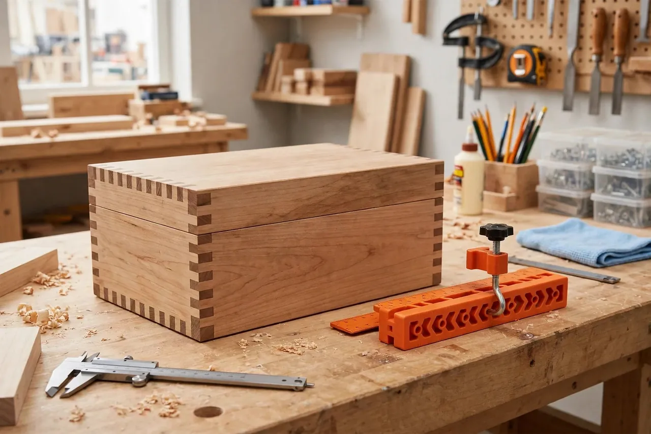
A box joint — rows of chunky interlocking fingers — is strong, handsome, and brutally honest. Every finger is the same width, every slot matches, and any error repeats down the corner like a rumor, growing until the last finger either will not close or wobbles loosely in its slot. Cut freehand or with a sloppy jig, the joint grades your work in public.
The principle of the jig is beautifully simple: an indexing pin the exact width of the slot your router bit cuts. Cut a slot, lift the board, drop that slot over the pin, cut the next slot. Spacing takes care of itself — provided the pin’s position relative to the bit is exactly right, and stays right.
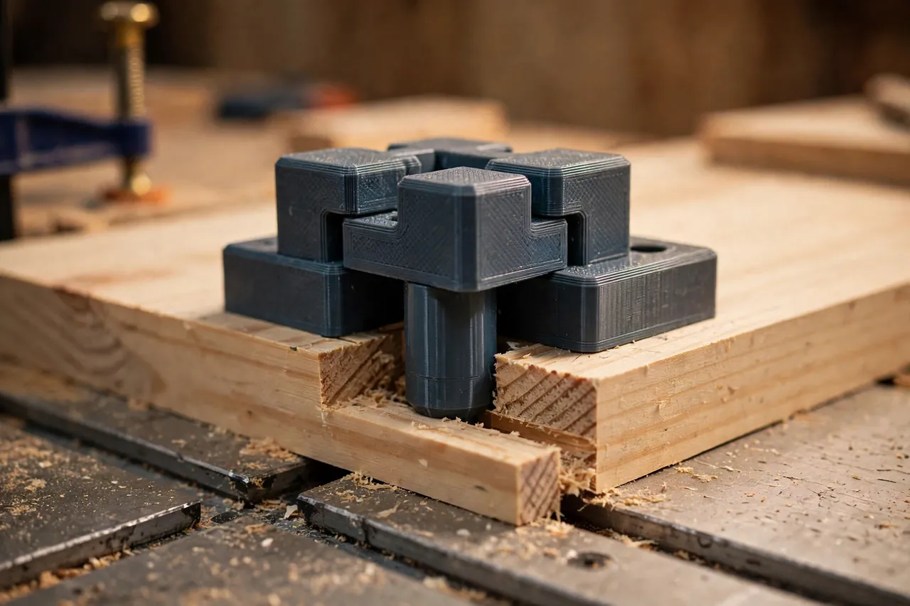
A 3D printed box joint jig makes that precision adjustable and repeatable at home. You print a sled or fence attachment with an indexing pin block you can swap for different bit sizes, plus fine adjustment so your first test corner already fits snugly.
This guide covers designing, printing, calibrating, and using the jig to cut finger joints for boxes, drawers, and trays in common board thicknesses.
What You Need
The jig works with a straight bit in a router table. Most designs are a sled that rides the fence or miter slot, with a tall backing fence and a replaceable pin block.
Materials and tools
- A home 3D printer with a build area of roughly 200 mm for sled and fence parts
- PETG filament for stiff, tough jig parts that survive repeated indexing
- A router table with a straight bit suited to your joint size, plus its fence
- The boards for your box, milled to final thickness and width, plus matching scrap in the same thickness
- A flat sled base or runner to suit your table, if your design uses one
- Calipers — this jig cannot be calibrated without them — and a steel ruler
- Clamps to hold boards firmly upright against the jig’s fence
- A push block to keep hands clear and boards moving steadily, plus eye and ear protection
- Sandpaper or a file for fitting pins and runners
PETG is the right keeper material: the indexing pin takes a tap from every board on every pass, and sled faces slide under load all session. PLA survives a test jig and proves geometry, but print the working version in PETG and verify its calibration again afterward.
Suggested print settings
- Layer height: 0.20 mm; the pin block benefits from 0.16 mm for crisp edges.
- Walls: 4 perimeters on the pin block, fence, and sled edges — these define accuracy.
- Infill: 40 to 50 percent, grid or gyroid, so parts stay rigid under clamping.
- Top and bottom layers: 4 or more for flat sled and fence faces.
- Orientation: Print the sled flat and the pin block with its working faces true to the bed or a machined edge.
- Supports: Design fences and sleds to print without supports on reference faces.
Print a test jig, cut a full test corner in scrap, and only then print final parts or cut good boards.
Design Considerations
Four numbers run this whole jig: bit diameter, pin width, pin-to-bit spacing, and board thickness. Get them consistent and the joint closes.
1. The indexing pin equals the slot
Your pin must match the slot your bit actually cuts, which is the bit’s true diameter in your material — measure a test slot with calipers rather than trusting the bit’s label. Model the pin to that measured width with the faintest slip clearance, about 0.05 to 0.1 mm under, so boards drop on and lift off without force but cannot slop sideways.
2. Pin position sets the finger
The distance from the pin’s near face to the bit’s near cutting edge equals one finger width — normally the same as the bit diameter, giving equal fingers and slots. Build in fine adjustment: a slotted pin block nudged by a screw, or shim pockets behind the block, so you can tune fit in hundredths. Box joints are famously adjustable in only one direction at a time: test, read the fit, nudge, retest.
3. A tall, square backing fence
Boards stand upright against a fence that must be dead square to the table and sled, or fingers taper and corners rack. Print the fence with gussets, check it with a square after assembly, and face it with a sacrificial strip of the project’s own material so the bit exits into backup wood and never blows out the back of a slot.
4. Sled guidance without play
Whether the sled rides the table’s miter slot, runs against the fence, or both, its travel must be straight with no side play. Model runners with 0.3 to 0.5 mm slip clearance and long contact lengths. Before printing final parts, slide your assembled sled through its full pass, router off, feeling for any rock or bind — your hands are the first calibration tool.
Step-by-Step: Printing and Assembly
- Choose your joint size — bit diameter and board thickness — for the first project.
- Cut a test slot in scrap with that bit and measure its true width with calipers.
- Model the jig — sled, square fence with gussets, swappable pin block at the measured width, and fine-adjust slots.
- Print test parts and assemble fully, including runner and sacrificial fence face.
- Check squareness and travel on the table, router unplugged: fence square, sled sliding freely with no side play.
- Set the pin position to one finger width from the bit, using calipers from pin face to bit edge.
- Adjust if needed. Correct pin width or position in the print or via the fine-adjust before cutting.
- Print keeper parts in PETG if tests were PLA, reassemble, and recalibrate from scratch.
Step-by-Step: Using the Jig to Cut a Box Corner
- Mill all boards first — same thickness, final widths, ends square. Box joints punish mixed thicknesses immediately.
- Set bit height to just over the board thickness, router unplugged while you set, using a depth gauge or test block.
- Cut a full test corner in scrap of the same thickness before touching project boards. Two short boards, joined, tell you everything.
- Cut board A’s first slot. Clamp it upright against the fence, flush to the sled’s starting stop, and pass it through the bit steadily with a push block, hands clear.
- Index and repeat. Lift the fresh slot onto the pin, reclamp, cut the next. Continue until slots march the full width, ending with the layout your plan calls for.
- Cut board B offset. Its first feature is a finger, not a slot: start it on the pin using a spacer or the offcut from board A’s first slot, per your design, so the two boards interlock rather than collide.
- Dry-fit the test corner. Fingers should slide together with firm hand pressure and a mallet tap at most. Read the fit: sloppy means the pin sits too far from the bit or too narrow; binding means the opposite. Adjust in tiny steps.
- Recut the test corner after each adjustment until it closes sweetly, then record the pin setting.
- Cut the real boards in one session without changing settings, keeping pairs together and checking the first real corner before completing the set.
Tips for Better Results
-
One setup, whole project. Bit height, pin position, and fence stay untouched from first test slot to last board. Most bad corners are born between sessions.
-
Label every board pair in pencil on a hidden face, so corners never get shuffled mid-session.
- Clamp the same way every pass — consistent pressure keeps boards seated identically against the fence.
- Keep a spare pin block ready in your common sizes, so a chipped pin never ends a session.
Common Mistakes to Avoid
- Trusting the bit’s printed size. Measure the slot it actually cuts. The pin copies the measurement, not the label.
- Changing two things at once. Pin width, pin position, bit height — adjust one, test, record. Simultaneous changes make calibration a lottery.
-
Cutting real boards after an unproven adjustment. Every change earns a fresh scrap corner first. Scrap is tuition; pay it gladly.
-
Skipping the sacrificial fence face. Bit exit without backup tears the back of every slot.
Care, Storage, and When to Choose an Alternative
Store pin blocks together in a labeled box, the sled flat, and the sacrificial faces replaced when tired. Brush chips from the pin and runner after each session — packed dust changes dimensions exactly where dimensions are the whole point. Recheck pin width against a fresh test slot each season.
For production box-making, very large joints, or dovetail-class work all day, a commercial metal box joint jig with micrometer adjustment justifies itself in speed and longevity. For home boxes, drawers, and trays — and for odd finger sizes no commercial jig offers — a calibrated printed jig closes corners as tightly as the care you put into its test cuts.
FAQ
What finger sizes work best for typical boxes?
Fingers matching common bits — 8 mm and 10 mm — suit small to medium boxes in 12 to 18 mm stock. A good rule: finger width near board thickness looks balanced and glues strongly. Scale up for big crates, down for jewelry boxes.
Why does my joint fit at one end and not the other?
Usually the fence is not square to the table or the sled has side play, so slots taper along the board. Check squareness with a tall square, snug the runner fit, and retest on scrap before blaming the pin.
Can I cut box joints in plywood?
Yes, with a sharp bit, a fresh sacrificial backing face, and steady feed. Plywood’s cross-grain layers chip eagerly at exits, so backing support and a test corner in the actual plywood are essential.
How tight should the dry fit be?
Snug hand pressure, seated fully with light mallet taps on a block — never a hammer campaign. Too loose wastes the joint’s famous glue strength; if fingers fall together under their own weight, nudge the pin setting and retest.
Conclusion
A box joint jig is a promise-keeping machine: it promises every slot will land one pin-width from the last, and a well-calibrated printed jig keeps that promise all the way around a box.
Print it stiff, measure the real slot, tune it on scrap until a test corner closes with a satisfying tap — then cut the good wood and watch four honest corners come together.
For joinery layout that leads into work like this, you may also enjoy our related guide, “3D Printed Doweling Jig: Make Straight, Strong Joints for Shelf and Table Repairs,” which covers another strong, simple joint for furniture repairs. And for holding glued boxes square while they cure, our guide “Assembly Squares: 3D Print Large Clamping Squares for Square Cabinets and Boxes Every Time” is the natural next print.