Introduction
Every workshop has the drawer: a jumble of screws in mixed lengths, diameters, and head styles, most of them unlabelled. Faced with joining two boards, you guess. Too long, and the tip pokes through the far side. Too short, and the joint pulls apart under the first real load. Too fat without a pilot hole, and hardwood splits along the grain.
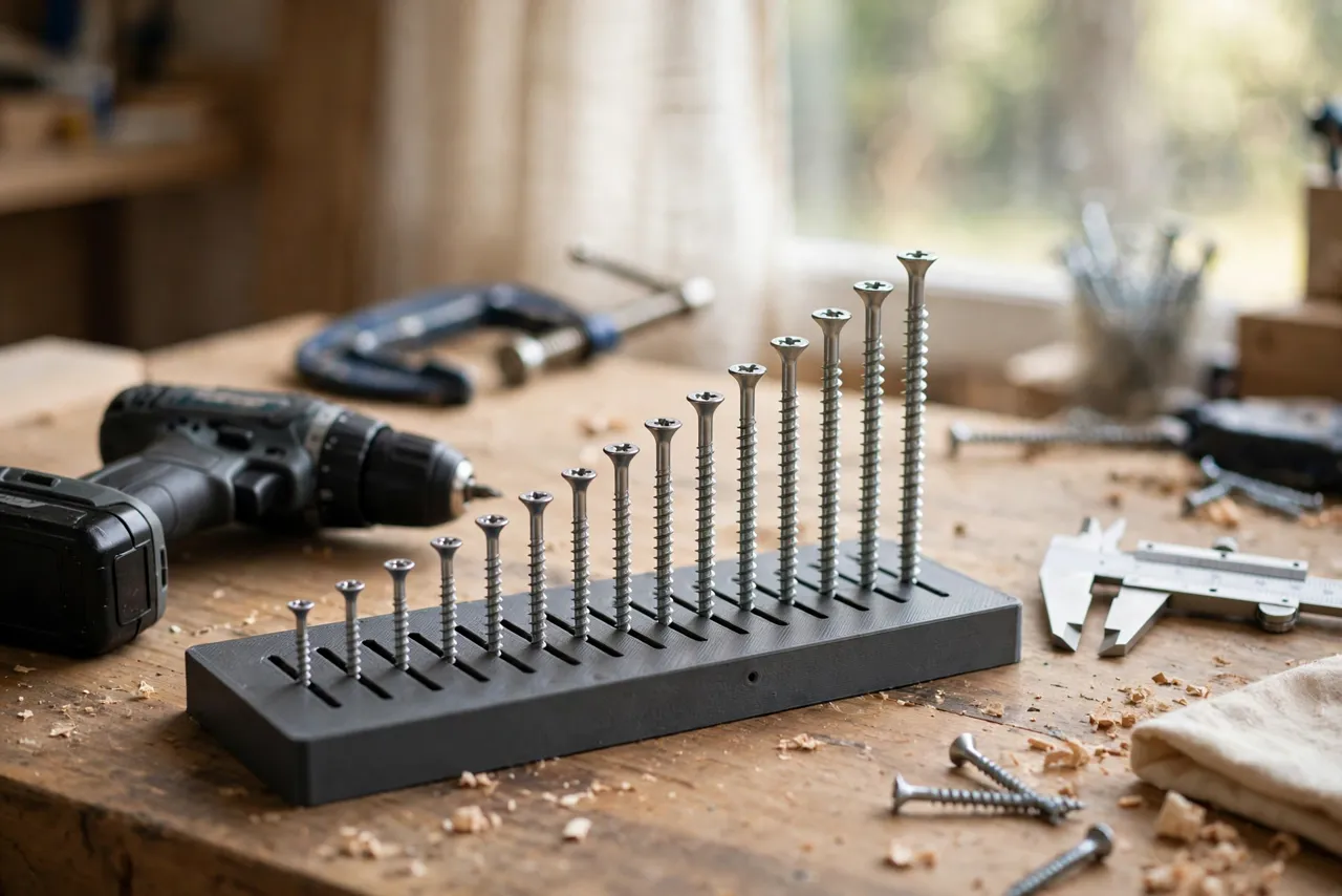
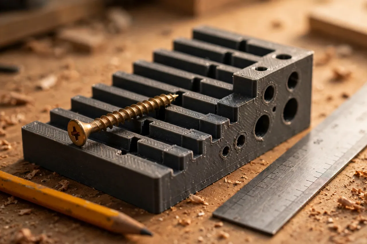
A 3D printed screw length and pilot hole gauge turns that guess into a thirty-second check. It is a flat bench board with stepped slots for measuring screw length, holes for checking shank diameter, and reference pilot holes you can test a drill bit against. Hold a screw up to the gauge, read the answer, and drill with confidence.
This guide covers designing, printing, and using your own gauge. It is a measuring aid only — it does not carry load, and it does not replace the screw manufacturer’s guidance for structural or load-bearing joints, where a manufactured fastener specification should govern.
What You Need
The gauge is a flat board, roughly 150 to 200 mm long, so any home printer can make it. The real work is measuring the screws you actually own.
Materials and tools
- A home 3D printer and PLA or PETG filament (either works; PETG survives a busy bench better)
- A sample of the screws you use most, in their common lengths and diameters
- Calipers or a steel ruler, a fine marker, and a pencil
- Your drill bits, for testing against the pilot reference holes
- A drill, a screwdriver, and scrap boards in the woods you join most
- Sandpaper or a small file for cleanup
Gather your screws before modeling. A gauge designed around screws you do not own is decoration; a gauge built around your actual drawer is a daily tool.
Suggested print settings
- Layer height: 0.20 mm for crisp slot edges.
- Walls: 3 to 4 perimeters.
- Infill: 30 to 50 percent, grid or gyroid.
- Top and bottom layers: 4 or more, so the measuring face stays smooth.
- Orientation: Print flat, measuring face up, for the cleanest slot edges.
- Supports: None for a flat board design.
Print a short test strip first with one length slot and one diameter hole, and check it against a known screw before committing to the full board.
Design Considerations
A good gauge answers three questions at a glance: how long is this screw, what diameter is it, and what pilot bit does it need. Design each section for one question.
1. Length slots
Length is measured from under the head to the tip for most wood screws — not including the head itself, which confuses many people. Cut stepped slots into one edge of the board, each slot depth matching a common screw length: 16, 20, 25, 30, 35, 40, 50, and 60 mm covers most home work. Drop a screw into the slots until one matches; the matching slot is the length.
Make the slots wide enough for the screw shank but narrower than the head, so the screw hangs by its head with the tip at the slot’s end. Add a small notch at each slot mouth so screws drop in easily.
2. Diameter holes
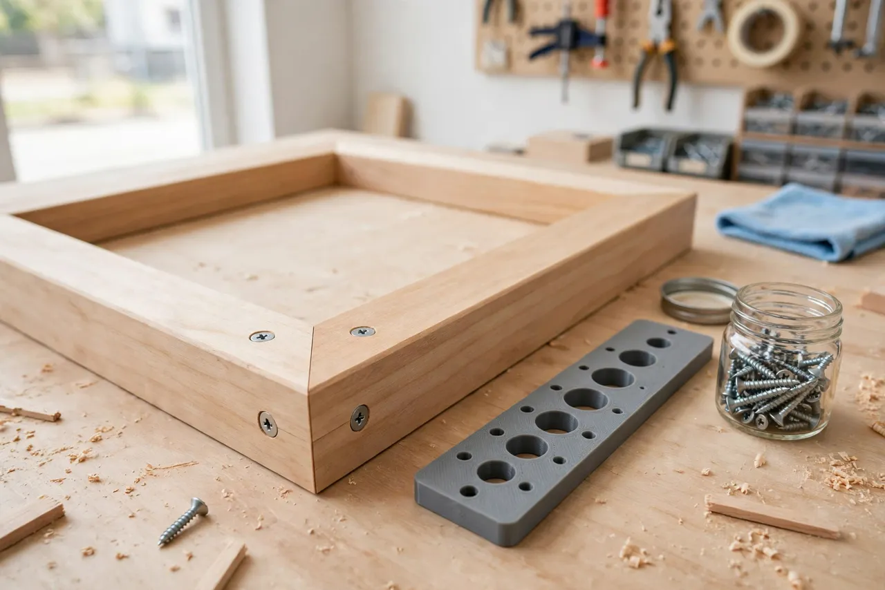
Drill or print a row of holes sized to common shank diameters — 3, 3.5, 4, 4.5, and 5 mm are a sensible set. Push a screw’s shank through the holes until one fits snugly; that hole is the shank diameter. This matters because pilot size follows shank diameter, not head diameter, and eyeballing the difference is unreliable.
Keep the holes clean and round. A hole printed with rough walls or elephant’s foot at the base reads a size small, so clean each hole by hand with the matching drill bit after printing.
3. Pilot hole reference
Next to each diameter hole, add a pilot reference: either a printed hole at the recommended pilot size for softwood and hardwood, or a labeled recess where you can test your drill bit. The usual rule of thumb is a pilot roughly the shank diameter for hardwood, and slightly smaller — about 70 to 80 percent of shank diameter — for softwood. Mark both on the gauge so you choose by wood type, not by habit.
This section is a starting guide, not gospel. Dense hardwoods, screws near board ends, and very large screws all deserve a test hole in scrap before the real workpiece.
4. The length rule, printed on the gauge
Add the joint rule to the board itself as raised or recessed markings: for a simple butt joint, the screw should pass through the first board and bury about two-thirds of its length in the second board, without poking through. A 20 mm top board plus a 30 mm bite into the second board means roughly a 50 mm screw. Having the rule on the gauge means you apply it at the bench, not from memory.
Step-by-Step: Printing and Assembly
- Sort your screws by length and diameter and note the sizes you actually use.
- Measure a sample of each size with calipers to confirm nominal sizes match reality.
- Model the board with length slots, diameter holes, and pilot references for your sizes.
- Print a test strip with one slot and one hole and verify it against known screws.
- Print the full gauge, clean every hole and slot by hand, and sand the measuring face flat.
- Label each slot and hole with a paint pen or printed markings.
- Test the whole gauge against your sorted screws, correcting any slot that reads wrong.
If a slot reads a size off, adjust the model by that amount and reprint the strip before redoing the full board. Small errors compound across a gauge.
Step-by-Step: Using the Gauge
- Measure the joint. Note the thickness of the first board and the thickness available in the second.
- Pick a target length. Add the first board’s thickness to about two-thirds of the second board’s thickness, and choose the nearest screw length that does not poke through.
- Check a candidate screw in the length slots to confirm its true length, not the size you assumed from the drawer.
- Check its diameter in the diameter holes.
- Read the pilot size for your wood type — hardwood or softwood — and select that drill bit.
- Test in scrap. Drill the pilot, drive the screw into scrap of the same wood, and check: no splitting, no poke-through, firm hold.
- Drill the real joint with the same bit and screw, and drive the screw firmly without overtightening.
That scrap test is the whole point. The gauge gets you to the right neighborhood; scrap confirms you are home.
Tips for Better Results
- Keep the gauge at the bench, not in a drawer. A gauge you have to hunt for does not get used.
- Sort screws after measuring. Once the gauge tells you a size, put that screw in a labeled tray — our related guide, “3D Printed Screw and Fastener Sorting Trays with Lids for Small Hardware,” is a good next step for the drawer itself.
- Recheck mixed batches. Screws from different brands with the same nominal size can differ by a millimetre or more.
- Mind the head style. Countersunk, pan, and round heads sit differently; length is measured from under the head, so confirm the head type matches your plan.
- Print a second gauge for the drill station. One at the bench and one near the drill press means the check happens wherever you are.
Common Mistakes to Avoid
- Measuring length including the head. For wood screws, length runs from under the head to the tip. Including the head overshoots by several millimetres.
- Skipping the pilot hole in hardwood. Hardwood splits, screws snap, and joints fail — all from a hole that takes ten seconds to drill.
- Using a pilot that is too large. An oversized pilot gives the threads nothing to bite, and the joint pulls apart. When in doubt, test both sizes in scrap.
- Choosing length by the drawer, not the joint. “The longest one I have” is not a fastening strategy.
- Trusting nominal sizes blindly. Verify with the gauge, especially for unlabelled bulk screws.
- Driving screws near board ends without a pilot. End grain and edges are where splits start; pilot and position matter most there.
Care, Storage, and When to Choose an Alternative
Brush dust out of the slots and holes, hang the gauge on a peg or keep it flat on the bench, and keep PLA versions away from heat. If a slot wears oversize from years of use, reprint the board — the model is the tool, the plastic is consumable.
Sometimes a commercial screw gauge or a set of drill-bit gauges is the better buy. If you work with a wide range of metric and imperial sizes daily, or need certified accuracy for fine work, metal gauges hold tighter tolerances. For home workshops with a handful of favorite sizes, a printed gauge is accurate enough and — unlike a store-bought one — matches exactly the screws in your drawer.
FAQ
How long should a screw be for joining two boards?
A good rule is the first board’s thickness plus about two-thirds of the second board’s thickness, without poking through the far side. So a 20 mm board joined to a 40 mm board wants roughly a 45 to 50 mm screw.
What pilot hole size do I need?
As a starting point, use the shank diameter for hardwood and about 70 to 80 percent of shank diameter for softwood, then test in scrap. Near edges and ends, always pilot, regardless of wood type.
Can the gauge measure bolts and machine screws too?
It can measure their length and diameter the same way, but pilot and clearance rules differ for machine fasteners — they need a clearance hole in the first part and a tapped or nutted second part, not a wood-screw pilot.
My screws keep snapping in hardwood. Is the gauge wrong?
Probably not — snapping usually means the pilot is too small, the screw is low quality, or the driver torque is too high. Enlarge the pilot slightly, test in scrap, and drive at lower speed with a properly fitting bit.
Conclusion
The screw drawer stops being a guessing game the moment you can measure what is in it. A printed gauge takes thirty seconds to use, costs almost nothing, and prevents the three classic screw failures: poke-through, pull-out, and split boards.
Print one for your actual screw sizes, keep it at the bench, and test every new combination in scrap. Once the screw is right, the next detail is getting it to sit flush — our related guide, “3D Printed Countersink Depth Setter: Screws That Sit Flush, Every Time,” picks up exactly where this one leaves off.